


|
 |
|
|
#1 |
|
Registered Member
Join Date: Jul 2003
Location: N. Florida
Posts: 129
|
DIY LED Array build
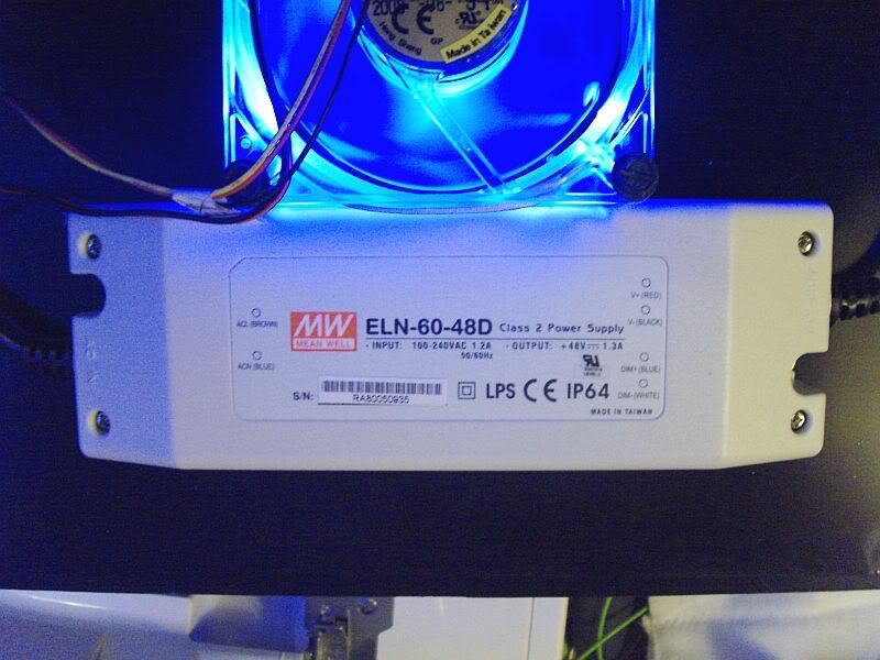
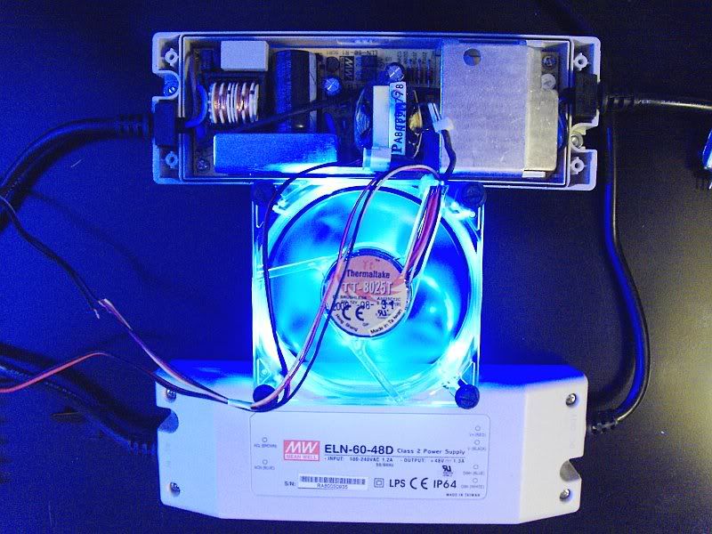
Hello, I have been lurking here on RC for a while and have been an avid reader of the DIY forum. I am very grateful for all of the instruction and great projects here, and hope that somehow posting my progress on my LED array build might contribute to this forum. I am not an electrical professional, and can not offer any advice along those lines, but I have posted a couple of questions on the large Led writeup thread and received answers to my engineering type questions. The goal of this project is to plan design and build a safe properly working LED array that will replace a 250 Watt Double Ended metal halide fixture I am currently running over my frag tank. I have started the testing and wiring phase of my project. The array will consist of Cree XRE white, and Royal blue leds. I originally wanted to run 2 strings of 15 Leds, but have been advised that 14 would probably be the safer number per string. I chose to use Meanwell LED drivers for my setup based upon their ability to wire into the mains power supply (standard 110 electrical outlet). As I have stated I do not have much electrical wiring exp. and wanted to avoid wiring multiple buckpuck drivers along with an additional power supply. Here is what I have wired so far......
|
|
|

|
|
|
#2 |
|
Registered Member
Join Date: Jun 2009
Posts: 1,307
|
Looking forward to seeing this!! I have 3 of those drivers myself, just waiting on the LED's before I start my build. If you could, take as many pics as you can of the wiring process etc

__________________
-Bob LaDouche "Out with the old, in with the new!" |
|
|

|
|
|
#3 |
|
Registered Member
Join Date: Jul 2003
Location: N. Florida
Posts: 129
|
Got it covered, I have already wired the Pot to both drivers and have 15 leds mounted and wired for testing..... I used a prebuilt pot so I did not have to try to engineer one from Radio Shack. Here is a picture of the pot.
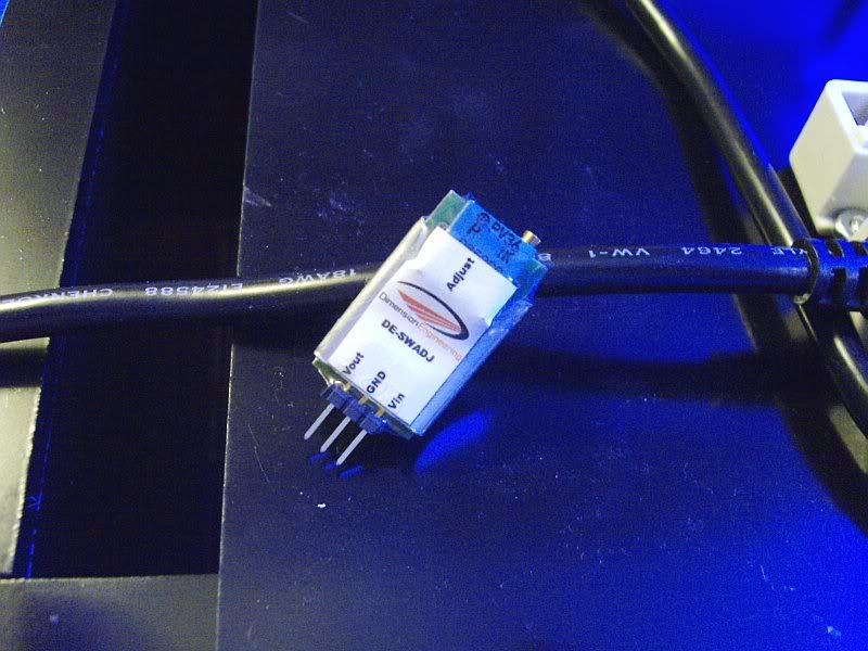 I know most people will want to order these drivers with the external dimming function. I am second guessing that decision, though because if you remove the cover these drivers already have pots for adjusting the output voltage, and current. I think it would probably be more convenient to use the dimmable version though because the pot can be mounted outside of the fixture. |
|
|

|
|
|
#4 |
|
Registered Member
 Join Date: Aug 2008
Location: US ARMY - El Paso TX
Posts: 3,678
|
fwiw....the dimmable version of the meanwells has a 4-wire output side wire (the same 2 wires for the LEDs & 2 to wire to the pot). pretty much the same as the wire leads on the buckpuck
as seen on the spec sheet for them: http://www.powergatellc.com/pdfs/ELN-60.pdf clickable thumb: 
__________________
Yes I hear voices in my head, but they speak spanish so I can't understand anything they say. there's no place like 127.0.0.1 It's a shame that stupidity isn't painful.... Current Tank Info: currently tankless....but planning an AIO |
|
|

|
|
|
#5 |
|
Registered Member
Join Date: Jul 2003
Location: N. Florida
Posts: 129
|
Thanks for linking that data sheet
 Next I have wired up the 0-10v pots to both drivers for dimming. I have a drawer full of wall warts that the electronics they powered died long ago. I had 2 of these and they seem to work, so if anyone knows that these will cause problems due to the voltage or amperage let me know. Next I have wired up the 0-10v pots to both drivers for dimming. I have a drawer full of wall warts that the electronics they powered died long ago. I had 2 of these and they seem to work, so if anyone knows that these will cause problems due to the voltage or amperage let me know.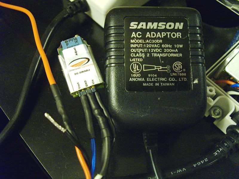 Also forgot to note where I procured the 0-10V pot....... http://www.dimensionengineering.com/DE-SWADJ.htm |
|
|

|
|
|
#6 |
|
Registered Member
Join Date: Jun 2009
Posts: 1,307
|
Is that letting you dim the lights pretty good? How do you have it connected to the driver? By that I mean how are the wires hooked up from the power supply to the voltage reg to the driver DIM + and -

|
|
|

|
|
|
#7 | |
|
Registered Member
Join Date: Jul 2003
Location: N. Florida
Posts: 129
|
Quote:
Take a look at the drawing that james3370 posted..... The output side of the driver has 4 wires....... Red= positive to LED string Black= negative from LED string Blue= supplied voltage from pot 0-10V marked on pot "Vout" White= negative tied to negative from wall wart soldered to "grnd" on pot then solder positive from wall wart to pot terminal labeled "Vin" Hope that makes sense 
|
|
|
|

|
|
|
#8 | |
|
Registered Member
Join Date: Jun 2009
Posts: 1,307
|
Quote:
 Correct me if I'm wrong. Correct me if I'm wrong. Power supply positive to V-In. Power supply negative to Ground White(Dim-) on driver to Ground. Blue(Dim+) on driver to Vout. |
|
|
|

|
|
|
#9 |
|
Registered Member
Join Date: Jul 2003
Location: N. Florida
Posts: 129
|
Correct JoshuaG.....
Update: I ordered the rest of the royal blue LEDs and optics that I need to finish this array and complete a second. I ordered the blues and optics from Anna at Etg Corp http://www.etgtech.com/ I got this source from another forum that has alot of info about LED lighting. The postman left me a registered package pickup notice today, and it says I can pickup my package that has arrived from Hong Kong. Translation: the 35 pieces of these http://www.dealextreme.com/details.dx/sku.2394 I ordered are here  Here is what I have mounted to my heatsink so far..... 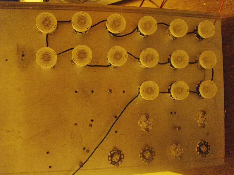
|
|
|

|
|
|
#10 |
|
Registered Member
Join Date: Jun 2009
Posts: 1,307
|
Ah you jerk, no wonder Anna was out of Royal Blues when I called her today, haha!
Nice pickup on the whites from DE, how long did it take for you to get them? |
|
|

|
|
|
#11 |
|
Registered Member
Join Date: Aug 2008
Location: Michigan
Posts: 98
|
Why are there 15 wired in a series? I thought the max these could run in a series on one string was 13 leds.
__________________
My 110g Peninsula Build http://reefcentral.com/forums/showthread.php?p=22592947#post22592947 |
|
|

|
|
|
#12 |
|
Registered Member
Join Date: Jul 2003
Location: N. Florida
Posts: 129
|
The Meanwell power supplies have adjustable current and voltage. Bottom left of this pic shows one of the adjustment screws, and the second is straight through the large aluminum block.
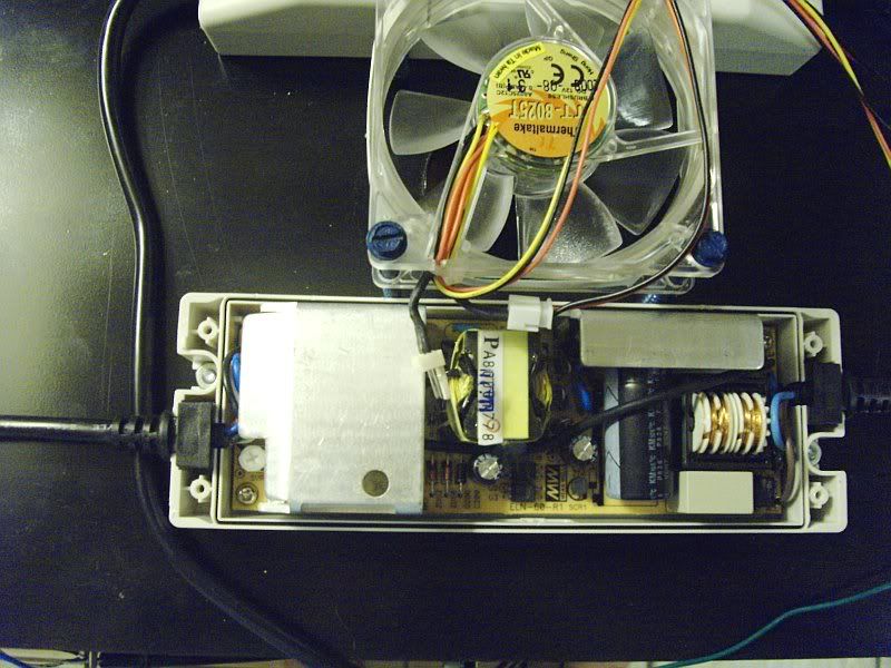 The first supply tested at 53.4V 800MA 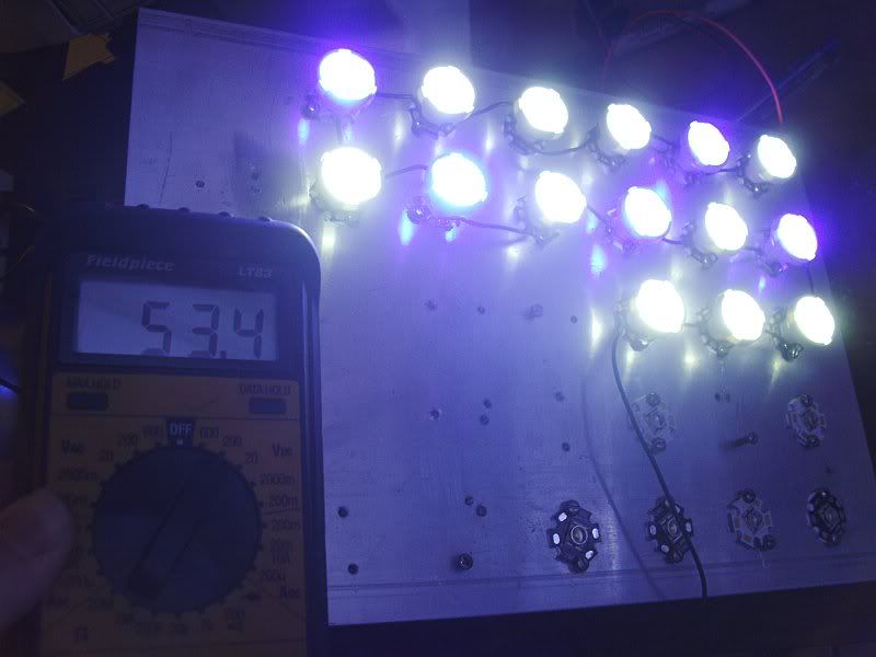 I thought I could push the conventional thought of only 13 LEDs per string, and run 15 per. I posted the question on the LED writeup thread and it seems that I might be safer at 14. I believe that these supplies can run 14 safely if they will drive 53 or 54V. The second driver is running at 54.5V  When I get the rest of the LEDs mounted later this week I will take the string down to 14 and test the voltage and current. If anyone wishes to see any additional specific pics of any of the components I have used this far please feel free to request....... |
|
|

|
|
|
#13 | |
|
Registered Member
Join Date: Jul 2003
Location: N. Florida
Posts: 129
|
Quote:
 I placed my order with Deal extreme on 6/11........ Free shipping with that pricing I will wait a few weeks  My wife is still not convinced how much money this project is really going to save in the long run. |
|
|
|

|
|
|
#14 |
|
Registered Member
Join Date: Jul 2003
Location: N. Florida
Posts: 129
|
Just got back from the Post office and have my package of white LEDs in hand......
First look: each led is individually bubble wrapped and in a bubble mailer. It looks like everything arrived in great condition. They ship them regestered air mail, and once they actually got them in stock they arrived in about one week. That makes for one  customer here. This is the second batch I have ordered from Deal Extreme and both experiences have been the same...... customer here. This is the second batch I have ordered from Deal Extreme and both experiences have been the same......Now for the receiving of the merchandise............ 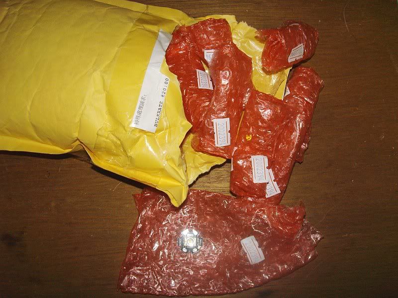 Also, I have some pics of how the optics work on the Leds. If you use the Cree leds I would strongly suggest that you buy the Cree optics they are only 1$ ea from ETG Corp and do not require any modification to mount. They are designed to "friction fit" on top of the mounted Led. 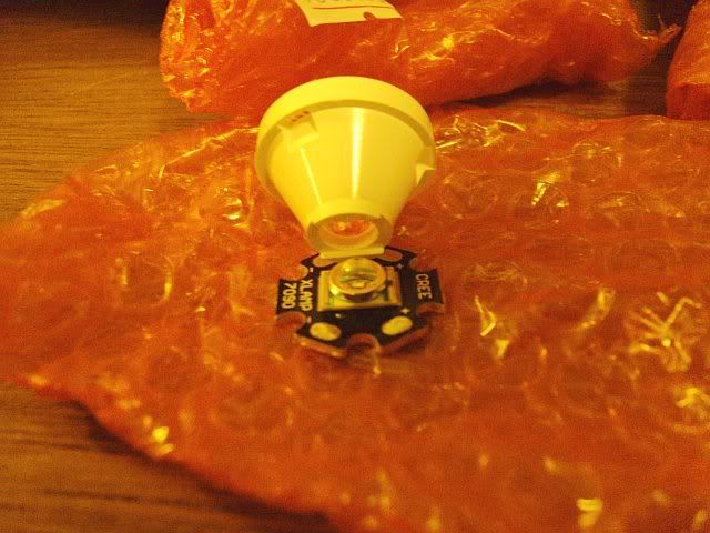 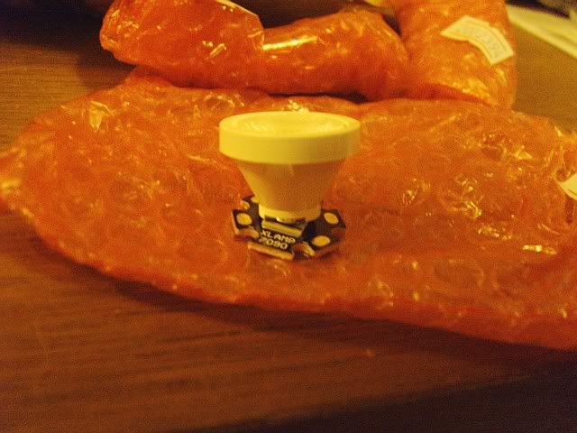 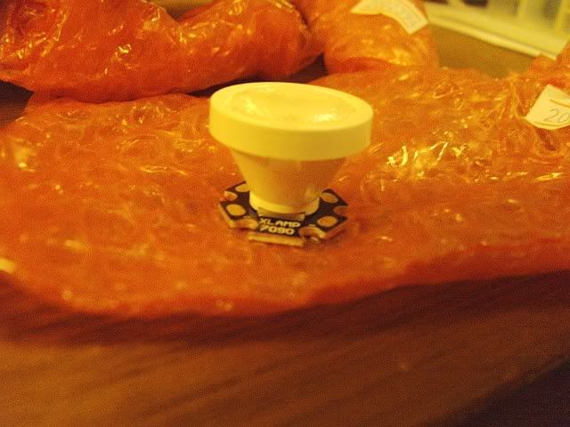
|
|
|

|
|
|
#15 |
|
Registered Member
Join Date: Jun 2009
Posts: 1,307
|
Nice!! Any plans on how you are mounting the heatsink to the tank?
__________________
-Bob LaDouche "Out with the old, in with the new!" |
|
|

|
|
|
#16 |
|
Registered Member
Join Date: Nov 2007
Location: Medina, Ohio
Posts: 126
|
could you send the exact link for the royal blues and also the optics?
|
|
|

|
|
|
#17 | |
|
Registered Member
Join Date: Jul 2003
Location: N. Florida
Posts: 129
|
Quote:
I have assembled a 1/4" acrylic fixture. It is just a basic rectangle with a flange that can be hung or flush mounted in a canopy. I am in the process of building a small fish room, and upgrading to a 120 gal tank so I wanted to keep my options open.....I have painted the inside of the fixture black and cut slots for forced air to move over the fins of the sink and out of the fixture. The bottom will be clear and act as a splash guard. Once I get the LEDs mounted and the wiring cleaned up I will take pics of the total package. |
|
|
|

|
|
|
#18 | |
|
Registered Member
Join Date: Jul 2003
Location: N. Florida
Posts: 129
|
Quote:
She is dealing with all of our orders here at RC and also at Nano reef. She is very familiar with what we reefers are looking for and responds quickly. If you are looking for specs on the royal blues you can look here... http://www.ledsupply.com/creexre-rb.php As far as the optics go just ask for 40 degree if you are looking for 250 watt metal halide type numbers or 60 degree for 150 watt. It just depends on your particular setup, to use optics or not and which degree. I am using a combination so I can put strong light down to sandbed and also not blast the corals that are higher up in the reef structure. That is the really neat thing about these LED fixtures, the ability to customize it to your needs....... HTH 
|
|
|
|

|
|
|
#19 |
|
Registered Member
Join Date: Jul 2003
Location: N. Florida
Posts: 129
|
Worked on the project some this evening, removed one of the white LEDs from my first string. Still have to drill and tap a few more holes, and wait for my Royal Blue LED shipment to arrive
 I will try to test the string tomorrow and post pics with the voltage and amperage measurements if my time permits........ |
|
|

|
|
|
#20 |
|
Registered Member
Join Date: Jul 2003
Location: N. Florida
Posts: 129
|
Update: I was able to remove one of the white LEDs from the original string of 15, so now I am planning to run 14 per
 I dialed down the dimming pot before I switched the power on so as not to put too much amperage through the string since I reduced the load. Then I slowly raised the external pot until it tested at 950MA. Next I adjusted the current adjustment pot inside the Meanwell until started to raise the current past 950MA and brought it back. So, what I hope I have accomplished is to set the max current that can flow through the string at 950MA. 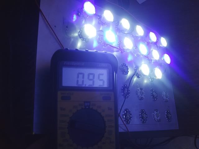 Now the voltage is reading 50.6V while driving this load. I guess the driver has regulated down to this due to what is wired up to it......if any of the Electrical gurus want to weigh in an let me know how this happens, and that I am now running in the "Safe Zone" I would be grateful....... 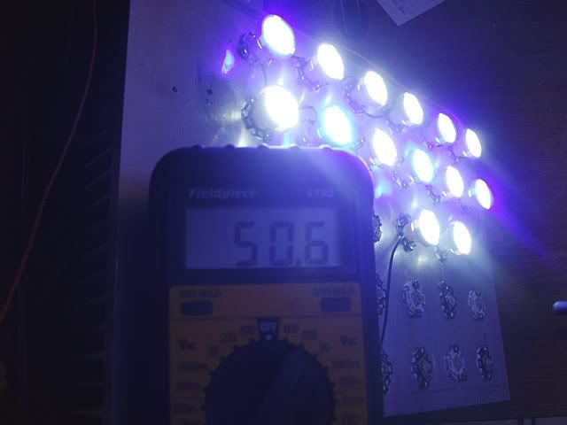 Also, as what I think will be extra insurance to prevent blown or shorted LEDs I placed an in line glass fuse holder and 1A glass fuse to the positive connection to the string. I purchased these at my local Radio Shack. Someone please weigh in if this will not protect my array do to some lack of understanding on my part..... 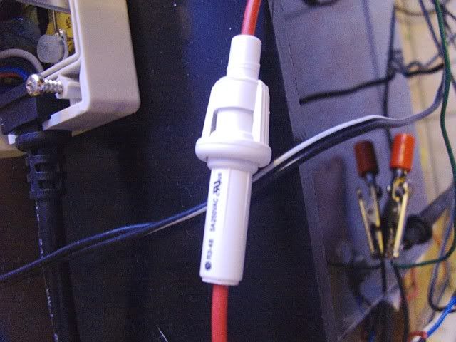
|
|
|

|
|
|
#21 |
|
Team RC Member
 Join Date: Sep 2003
Location: NY
Posts: 17,749
|
sphil, that driver is designed with a max output of 48v. The voltage reading you will get on the output side the driver is determined purely by the current and the specifications of the LEDs. If you have an LED with a forward voltage of 3.7V at 1A, you'll see 3.7V if you put 1A through it.
So, if you have 15 LEDs with a certain forward voltage and drop down to only 14 of those on the same driver set to the same current, you'll see the output voltage drop by 1 LED's forward voltage. in other words, the 48v spec for your driver is a max rating, the actual voltage it puts out will depend on what it's driving. Since you are seeing 50.6V with 14 LEDs at 950mA, we know that you are seeing a forward voltage of just over 3.6V per LED. This is pretty close to the spec for XR-E (3.7V @ 1A) so it's inline with what should be expected. I think you are seeing why people normally drive 13 LEDs on that driver - IMHO you're running it beyond the design spec and might run in to problems. If you really want to keep 14 (or even 15) LEDs on each driver, you could turn the current down - the forward voltage of an LED will decrease as current decreases, so at some point you could get under the 48V max. Of course, you could also just remove another LED.
__________________
Inconveniencing marine life since 1992 "It is my personal belief that reef aquaria should be thriving communities of biodiversity, representative of their wild counterparts, and not merely collections of pretty specimens growing on tidy clean rock shelves covered in purple coralline algae." (Eric Borneman) |
|
|

|
|
|
#22 |
|
Registered Member
Join Date: Jul 2003
Location: N. Florida
Posts: 129
|
Ok, I think I understand the principle you are explaining regarding the drop in Voltage, but regarding the max voltage of the supply the spec sheet says "ELN-60-48 48V 1.3A 43.2 ~ 52.8 VDC Adjust Range." If I run the string inside of that range, will I have any problems when running close to the high end of the Manufacturer published spec? When I adjust the driver to the max voltage with no load I read 54.5V. So from what I have read this is leaving almost 4V of headroom on this specific driver. Should this not be sufficient to prevent any problems?
__________________
Click the red house to visit my LED build thread......... Phil Current Tank Info: 55 gal mixed reef w/100 gal rubbermaid sump W/ Vertex Alpha skimmer |
|
|

|
|
|
#23 |
|
Team RC Member
 Join Date: Sep 2003
Location: NY
Posts: 17,749
|
Basically, the way it works is that your driver will put out whatever V the LEDs "need" to hit the current you have it set at. So, you could run a single LED off that driver, and you'd see it putting out around 3.7V, for instance. Add LEDs, and V output increases to keep the current constant.
The "VDC Adjust Range" is referring to using the voltage adjustment (inside the case) to modify the maximum voltage the unit can put out, similar to the "Vout" adjustment trim pot on many DC power supplies. Though, I would be really nervous about trying to adjust voltage on a constant current driver, since I don't know how the adjustment would play out. (I've never used or really looked at a constant current driver that even had any sort of voltage adjustment, so I'm just not sure how it's implemented on the mean wells.) Also, in the end, it IS a 48V driver and you are running above that - the datasheet specs a certain % over voltage limit, and clearly you are within that (or else it would be shutting down), so in a way you're safe. But if it were me, I'd be much happier running it under specs, instead of under the max adjustment/over-voltage tolerance above spec.
__________________
Inconveniencing marine life since 1992 "It is my personal belief that reef aquaria should be thriving communities of biodiversity, representative of their wild counterparts, and not merely collections of pretty specimens growing on tidy clean rock shelves covered in purple coralline algae." (Eric Borneman) |
|
|

|
|
|
#24 |
|
Registered Member
Join Date: Jul 2003
Location: N. Florida
Posts: 129
|
Thanks, just trying to squeeze as much dollar to watt efficiency out of this setup as possible without causing damage to my components. Because after all, blowing up a driver would definately hurt the dollar efficiency by having to buy another. I am building this as a prototype, and with success I have approval from my comptroller(wife) to build another to light my 120 upgrade.....

__________________
Click the red house to visit my LED build thread......... Phil Current Tank Info: 55 gal mixed reef w/100 gal rubbermaid sump W/ Vertex Alpha skimmer |
|
|

|
|
|
#25 |
|
Registered Member
Join Date: Jul 2003
Location: N. Florida
Posts: 129
|
So it is time to start soldering up the next string of LEDs.......
I had not done much soldering previously, so I had to purchase a soldering iron for this project. It is a 40 watt iron, and it has worked very well so far. 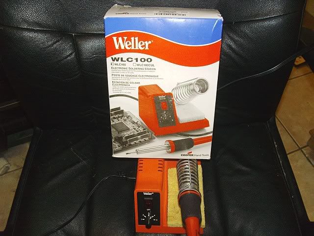 Here is the flux and solder that I am using to do all of the soldering...................  I will try to detail the soldering process I have used, because to those of us who do not have much practice with a iron this seems a little daunting 
|
|
|

|
 |
|
|